Texas Instruments BQ28Z610 GaugingStatus()[REST] is not set
If you read the GaugingStatus()[REST] flag via the I2C protocol from the BQ28Z610 device and it never becomes high, then just check again which bit you read, because the documentation from TI has many typos, and this is one of them.
Proteus Animation Options
Texas Instruments Gas Gauging Device BQ28Z610 FETControl(), ChargeFET(), DischargeFET()
The information about the relationship between sealing/unsealing the device and FETControl() with ChargeFET() and DischargeFET() is not clear enough in the Technical Manual. Therefore, I decided to address this gap with this article.
Seal/Unseal device, FETControl() and ChargeFET(), DischargeFET()
- First of all: none of FETControl(), ChargeFET(), DischargeFET() can be executed while device is Sealed.
- Ok, let's unseal the device. Now, while the ManufacturingStatus[FET_EN] flag is high neither ChargeFET() nor DischargeFET() can be executed.
- Let's call FETControl() to clear the [FET_EN] flag. Charging and Discharging FETs are now disabled. You may check this by the flags: OperationStatus[XCHG] and OperationStatus[XDSG], which are raised. I call this state "blocked unsealed".
- If you now seal the device, then charging and discharging FETs will remain disabled. To return the device to the previous state, you should unseal it. I call this state "blocked", because FETs cannot be enabled again while the device is Sealed.
- Let's return to the previous state, "blocked unsealed". At this state you may operate FETs by calling ChargeFET() - to enable Charging FET and DischargeFET() - to enable Discharge FET.
- If the device becomes sealed while one of the FETs is enabled, then both FETs will become disabled. This happens because when ManufacturingStatus[FET_EN] = 0, none of the FETs can be enabled in sealed mode.
- And the final state is: when you call ChargeFET() after DischargeFET(), or vice versa, both FETs become enabled. However, if the device is sealed, then both FETs will become disabled.

|
| The relationship between the seal/unseal device and FETControl() with ChargeFET() and DischargeFET() |
Charging does not work when I call ChargeFET()
I found one peculiarity that was not mentioned in the documentation. I don't know why it was designed this way, but I would like to share it with the community.
There are no issues with calling DischargeFET() it works just fine. However, this isn't the case for ChargeFET(). So let's take a closer look at the states:
- The device is charging. Current() = 90 mA.
- Call FETControl() to clear the [FET_EN] flag. Charging FET is disabled now, as well as Discharging one, so Current() = 0.
- Call ChargeFET(). Charging should continue, but it's not happening. Current() = 0.
- Let's call DischargeFET() to enable Discharge FET. Now charging continues. Current() = 131 mA.
- Let's call DischargeFET() again to disable Discharge FET this time. Charging does not stop. Current() = 119 mA.
So Charging works only if Discharge FET was previously enabled. This behaviour is strange, but now you are informed about the process.
 |
| Usage of the ChargeFET() and DischargeFET() |
References
- Texas Instruments Technical Reference Manual: https://www.ti.com/lit/ug/sluua65e/sluua65e.pdf
- The diagrams were created using the yED software from yWorks: https://www.yworks.com/products/yed
Why BQ28Z610 function Current() returns 0 mA
Fixing 0 mA Current Readings
on the BQ28Z610 Device
Custom driver for the BQ28Z610 device was connected directly via I2C. It is possible to obtain non-zero values from functions Voltage(), Temperature() and other. Charging and Discharging are allowed, current flow can be seen on the ammeter, but functions "0x0C/0D Current()" and "0x14/15 AverageCurrent()" always return [0x00, 0x00].
You may try increase actual current up to 1 A.
You may try to call function "12.2.15 AltManufacturerAccess() 0x0021 Gauging" to turn on the gauging of the current.
If nothing else helps, you should check your hardware circuit and test the sense resistor (Rsense). To do this, pass some current through it and measure the voltage across it in millivolt fractions.
For example, Rsence = 2m0 (2 milliohms). So current 1 A will produce 2 mV on it: "1 A * 2 mO = 2 mV".
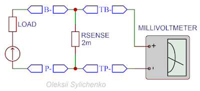
To exclude the software component of the test, you need to:
- Disconnect load and charger.
- Take constant current source, at least 1 A, bigger - better.
- Take some load. You may use adjustable load to control the current.
- Take millivoltmeter, which can show fractions of the millivolt, or just microvoltmeter.
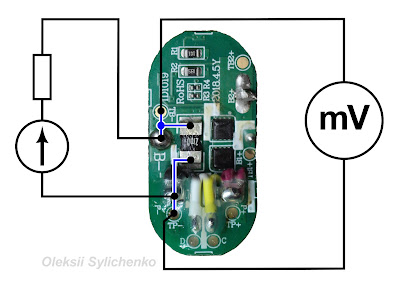
- Connect "current source +" and + of the load.
- Connect "load -" to the "B-" terminal.
- Connect "current source -" to the "P-" terminal (charger/load negative connection).
- Read voltage on the sense resistor on the test pins: "TB-" and "TP-" - it should correspond to the current.
- Change current and read voltage again - it should be changed as well.
-
Reverce polarity of the current source - voltage on the Rsence resistor
should become negative as well.
|
|
Test circuit independent |
|
|
Test schema independent |
If the voltage is 0, then check your main circuit and try to clean it a little bit and remove any stickers - perhaps during production, sense resistor connections were shorted.
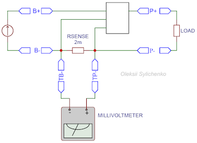
If the voltage is correct then build another test circuit:
- Connect the battery to the BAT terminals.
- Temporarily short terminals BAT+ and PACK+ to activate the microchip.
- Connect the load to the PACK terminals.
- Read voltage on the sense resistor - it should correspond to the current.
- Change current and read voltage again - it should be changed as well.
|
| Test circuit via BQ28Z610 |
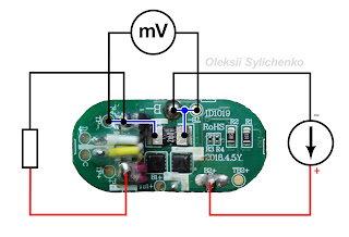 |
| Test schema via BQ28Z610 |
If the voltage is 0 this time then the problem is in the microchip, the possibly it's a software issue, maybe it shorts the sense resistor by some configuration - but it was not my case, so I cannot confirm or deny if such a case possible.
Was used microchip BQ28Z610 at the battery pack from "JBL Xtreme 2", with the Device Name from the Data Flash: "ID1019-A-M26-28z610".
Resources
- BQ28Z610 Technical Reference Manual (Texas Instruments): https://www.ti.com/lit/ug/sluua65e/sluua65e.pdf
-
Прошити LGT8F328P-SSOP20 як звичайну Arduino Pro Mini через інтерфейс SPI (MOSI, MISO, SCK, SS) не можна, але можна прошити по інтерфейсу...
-
Ever wondered how Google works its magic with Maps? 🗺️ They've got these cool Maps URLs that hold location secrets, like where to fi...


